Drawing Views

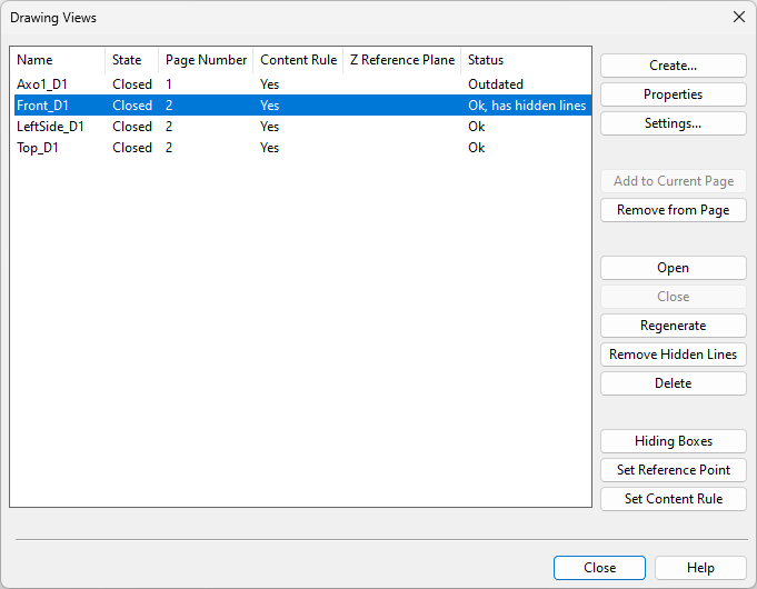
Select Home tab > Views group > Drawing views > Drawing views or click the Drawing views button to open the Drawing Views dialog, where you can manage drawing views and their properties. You can hold down Ctrl or Shift to select multiple views from the list.
Create
In the Drawing views dialog, the Create button opens a menu for creating different kinds of drawing views.
Standard views | Default views | Custom view | View from point 1 to point 2 | Copy selected drawing views | Copy views from elsewhere | Standard E-projections | New view direction
Standard views
You can use this command to create shaded drawing views with either predefined or custom view direction.
Do the following:
-
In the Drawing Views dialog, select Create > Standard views.
-
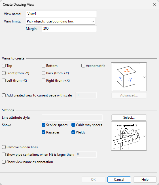
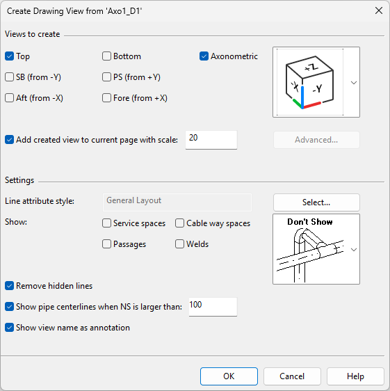
In the Create Drawing View dialog, specify what kind of views to create.
Setting
Description
View name
Enter a descriptive drawing view name.
A view type-specific identifier will be added after this name. For example, if the name is 'MyView' and you create a Top view and an Axonometric view, the resulting view names will be 'MyView_Top' and 'MyView_Axo'.
View limits
Select how to define the view limits:
-
Select this option to define the view limits by picking two corner points from the 3D model.
-
Pick objects, use bounding box
Select this option to define the view limits by selecting a set of objects from the 3D model. The view displays only the selected objects and uses their bounding box as the view limits.
-
Custom direction from P1 to P2
Select this option and click Pick to define the view limits based on two points you pick from the 3D model. In the additional settings, you can specify whether the view displays a set of selected objects or all objects within the view limits.
Select additional options for view limits, where available.
Specify a margin (millimeters) to add empty space around the bounding box of the included objects.
Select this option if the new view includes only objects that you select during creation. Otherwise, when the view is created, it initially includes all objects within the view limits, but you can adjust this with content rules later.
Use model Y-axis as up direction for horizontal top and bottom views
Select this option to use the Y-axis as the up direction in horizontal top and bottom views. Otherwise, when you close this dialog, you are prompted to define the up direction in the model.
Views to create
<view direction>
Select which views to create, such as Top and Axonometric. If creating an axonometric view, select the view direction by choosing a predefined cube or Custom from the drop-down menu.
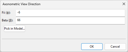
When the view type is Axonometric and view direction is set to Custom, clicking Advanced opens the Axonometric View Direction dialog for defining Fii (f), meaning the rotation angle in the horizontal plane, and Beta (b), meaning the elevation angle from the x-axis.
Select this option and define the scale to insert each new drawing view to the active page immediately after closing this dialog.
Settings
Line attribute style
Click Select to choose one of the available Line Attribute Styles for the new drawing views.
Show
Select which of the following object types to also display in the new drawing views:
-
Service spaces
-
Passages
-
Cable way spaces
-
Welds
For displaying insulation, select Don't Show, Transparent 1, Transparent 2, or Opaque.
Remove hidden lines
Select this option to remove hidden lines from the new drawing views.
Show pipe centerlines when NS is larger than
Select this option and specify a nominal size (millimeters) to display the centerline when the pipe's nominal size exceeds this value.
Show view name as annotation
Select this option to display the name and scale of each drawing view below the geometric extents of the view. This text uses the annotation property defaults of the active page, and although it can be edited with drafting tools, renaming or rescaling the view will reset the text to default.
-
-
Click OK.
-
Depending on view type, you may be prompted to pick two corners that define the view limits, to pick the objects to display in the views, or to define the up direction.
-
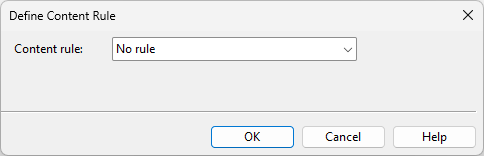
In the Define Content Rule dialog, select whether to apply content rules to the new views.
-
To display the currently defined objects, select No rule and click OK.
-
To specify which objects to display, select Define query for visible objects, define the query as described in Create, and click OK.
-
-
If you selected the Add created view to current page with scale option, you are prompted to pick a location for each new view in the active page. Otherwise, you must add them manually using Add to Current Page.
Default views
Tip: This tool will be removed in a future version. Start using Standard views instead.
Create > Default views opens the Create Default Views dialog where you can create one or more shaded or wireframe drawing views that use a predefined viewing direction. For details, see Default Views.
Custom view
You can create drawing views by defining the view and its contents completely manually.
Do the following:
-
In the Drawing Views dialog, select Create > Custom view.
-
In the Create View dialog, enter a name for the new view, and click OK. If a view by that name already exists, you are prompted to overwrite it.
-
In the Set Properties of View dialog, define settings for the new view, and click OK.
View from point 1 to point 2
Tip: This tool will be removed in a future version. Start using Standard views instead.
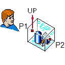
You can create a set of wireframe drawing views that show a set of objects from different angles. You can create up to five different views at the same time: a view that faces a user-defined direction, a top view, a view from right to left, a view from left to right, and an axonometric view.
The limits of each view are defined by the bounding box of the visualized objects, the view direction, the up direction, and (optional) user-defined margin.
Do the following:
-
In the Drawing Views dialog, select Create > View from point 1 to point 2.
-
Select the objects to include in the view and press Enter.
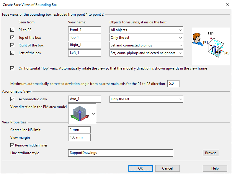
The Create Face Views of Bounding Box dialog opens.
-
To create a view that faces a specific direction, define the following settings:
-
Seen from – Select whether the view direction is from point 1 to point 2 or from the top, right or left side of the bounding box.
-
View name – Enter a descriptive name for the view.
-
Objects to visualize, if inside the box – Select which of the objects that are inside the bounding box to visualize in the view:
-
All objects – All objects.
-
Only the set – Objects you initially selected into the set.
-
Set and connected pipings – Objects you selected and pipes that are connected to those objects.
-
Set, conn. pipings and selected neighbors – Objects you selected, pipes that are connected to those objects, and additional objects that you will select later on during this procedure.
-
-
On horizontal "Top" view… – Select this option if you are creating a top view and you want the 3D model's Y direction to point upward in the view frame.
-
Maximum automatically corrected… – Define how many degrees the view direction can deviate from the nearest main axis direction. If the deviation is less than this value, the view is aligned with the coordinate axes of the 3D model.
-
-
To create an axonometric view, define the following settings:
-
Make sure Axonometric view is selected.
-
Enter a descriptive name for the axonometric view.
-
Select the view direction of the axonometric view from the menu.
-
Select which objects to visualize in the axonometric view.
-
-
Define the view properties:
-
Center line NS limit – Define the smallest nominal size for showing the centerline of pipes.
-
View margin – Define how many millimeters of extra space to add around the bounding box of the view.
-
Remove hidden lines – Select this option to allow hidden lines to be removed when the view is created.
-
Line attribute style – This option is shown when you are creating a drawing view. Click Browse to select a specific line attribute style for the drawing views to be created.
-
-
Click OK.
-
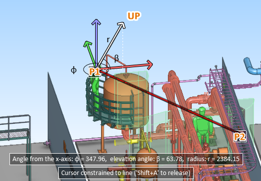
Pick a start point (P1) for the vector that defines the view direction.
-
Pick an end point (P2) for the vector that defines the view direction.
-
Define the up direction of the view. The program tries to select a suitable direction and locks the direction—press Ctrl+A if you want to release the cursor and select another direction. Click or press Space to accept the direction.
-
If you chose to include "selected neighbors" in any of the views to be created, select those additional objects and press Enter.
The specified views are created.
Copy selected drawing views
You can create one or more copies of existing drawing views.
Do the following:
-
In the Drawing Views dialog, select the view or views you want to copy. Hold down Shift or Ctrl to select multiple views.
-
Select Create > Copy selected drawing views.
-
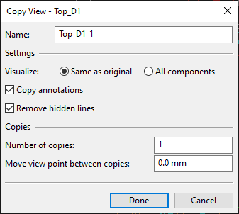
In the Copy View dialog, define properties for the copies of the first view.
-
Name – Enter a name for the new view. If creating multiple copies, the name of each additional copy will be appended with an underscore and running number.
-
Visualize – Select whether the new views should contain the same components as the original view or all components.
-
Copy annotations – Select this option to include the annotations of the original view in the new views.
-
Remove hidden lines – Select this option to remove hidden lines from the new views.
-
Number of copies – Enter the number of new views to be created.
-
Move view point between copies – You can set the viewpoint to be incrementally moved for each new view. Specify the increment in millimeters—a positive number moves the viewpoint forward, while a negative number moves it backward.
-
-
Click Done.
-
Repeat steps 3–4 for each additional view you selected to copy.
Copy views from elsewhere
You can copy wireframe work views or drawing views to the active document. If the work view has annotations or reference drawings, they are not copied.
Note: To copy a newly created work view, you must either save the area model or close the new view first.
Do the following:
-
In the Drawing Views dialog, select Create > Copy views from elsewhere.
-
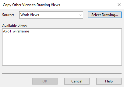
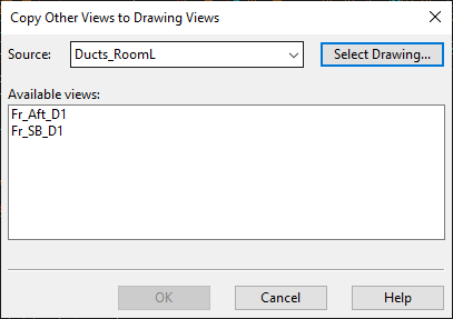
In the Copy Other Views to Drawing Views dialog, select the views to copy:
-
To copy work views, select the work views from the list pane.
-
To copy drawing views from another document, click Select Drawing, select the document from which to copy drawing views, and then select the views from the list pane.
-
-
Click OK.
-
To stop copying views, click Cancel.
-
Use Add to Current Page to insert a copied view to the active page.
Standard E-projections
Tip: This tool will be removed in a future version. Start using Standard views instead.
You can create standard European projections traditionally used in 3D design from selected objects. The generated views are placed on the page based on two user-defined corner points. Hidden lines are automatically removed. You can place several projection sets to one page. Also drawings with multiple pages are supported.
After the insertion, you can relocate the projection views and change their scale. You can modify these views with the normal view and visualization commands and annotate them in the same way as other drawing views.
Prerequisites
-
An open work view.
Do the following:
-
In the Drawing Views dialog, select Create > Standard E-projections.
-
You might be prompted to select which Annotation Property Defaults to use on the active page. Select the one to use and click OK.
-
Select the objects to be visualized from the active work view and press Enter. The Create Standard E-Projections dialog opens.
-
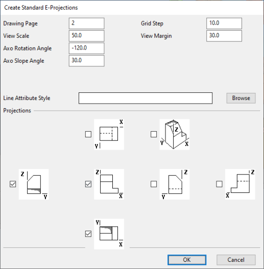
Define the settings:
 Show/hide details
-
Drawing Page – Enter the number of the drawing page to which to assign the projections. The active page is the default. If you enter the number of a non-existing page, a new page will be added to the drawing and you are prompted to edit the page-specific fields and select the Annotation Property Defaults to use.
-
View Scale – Define the view scale. This scale is used in all the individual projection views to be created.
-
Axo Rotation Angle – Define the rotation angle for axonometric views. The default value is -120.
-
Axo Slope Angle – Define the slope angle for axonometric views. The default value is 30.
-
Grid Step – Define the grid step. The value must be between 1 and 100, and the default value is 10.
-
View Margin – Define the margin to include to the view limits, outside the objects to be visualized. The value must be between 1 and 1000, and the default value is 30.
-
Line Attribute Style – Select the style to use for the projections. For more information, see Select line attribute style.
-
Projections – Select the projection types to be created as separate drawing views. The drawing vies will be named in the format "ProjectionTypeXXYY" where XX is the page number and YY is the ordinal number of the projection type on that page, such as "Axo0101".
-
-
Click OK.
-
On the target page, the projection area is shown as a rectangle and you can move it to the intended location:
-
Pick the point where you want the top-left corner (origin point) of the projection area to be located.
-
Pick the point where you want the bottom-right corner of the projection area to be located.
(The size of this rectangle you draw here does not affect the scaling of the projection views inside the area.)
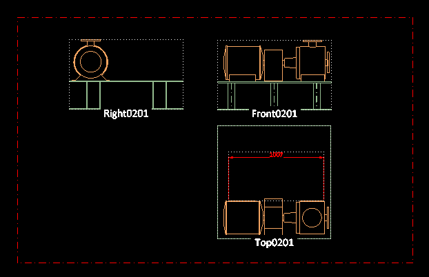
The projection area is drawn as a dashed rectangle and the projections are located in that area, in the same order that they were presented in the settings dialog.
-
-
You can continue creating additional standard projections or press Esc to exit the tool.
New view direction
You can create additional drawing views that show the objects of an existing drawing view from different directions.
Do the following:
-
In the Drawing Views dialog, select Create > New view direction.
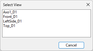
-
In the Select View dialog, click the name of the view that defines the objects to display in the new views.
-
In the Create Drawing View from '<view>' dialog, specify what kind of views to create.
Setting
Description
Views to create
<view direction>
Select which views to create, such as Top and Axonometric. If creating an axonometric view, select the view direction by choosing a predefined cube or Custom from the drop-down menu.
When the view type is Axonometric and view direction is set to Custom, clicking Advanced opens the Axonometric View Direction dialog for defining Fii (f), meaning the rotation angle in the horizontal plane, and Beta (b), meaning the elevation angle from the x-axis.
Select this option and define the scale to insert each new drawing view to the active page immediately after closing this dialog.
Settings
Line attribute style
Click Select to choose one of the available Line Attribute Styles for the new drawing views.
Show
Select which of the following object types to also display in the new drawing views:
-
Service spaces
-
Passages
-
Cable way spaces
-
Welds
For displaying insulation, select Don't Show, Transparent 1, Transparent 2, or Opaque.
Remove hidden lines
Select this option to remove hidden lines from the new drawing views.
Show pipe centerlines when NS is larger than
Select this option and specify a nominal size (millimeters) to display the centerline when the pipe's nominal size exceeds this value.
Show view name as annotation
Select this option to display the name and scale of each drawing view below the geometric extents of the view. This text uses the annotation property defaults of the active page, and although it can be edited with drafting tools, renaming or rescaling the view will reset the text to default.
-
-
Click OK.
-
If you selected the Add created view to current page with scale option, you are prompted to pick a location for each new view in the active page. Otherwise, you must add them manually using Add to Current Page.
Modify
In the Drawing views dialog, the Modify button opens a menu with the following tools.
View area | Add objects, extending view box | Advanced view properties
View area
You can modify the view limits of a drawing view. If the view has a filter box, the tool prompts you to choose how to handle it.
Prerequisites
-
An open work view.
Do the following:
-
In the Drawing Views dialog, select the drawing view to modify.
-
Select Modify > View area. The active work view is displayed.
-
If the view is axis-aligned, do the following:
-
Move each required corner of the view area by first picking the corner and then picking a new location for it.
-
Press Enter to confirm the changes.
-
-
If the view is axonometric, do the following:
-
The first corner of the 3D box is automatically selected. Pick a new location for it.
-
The opposite corner of the 3D box is automatically selected. Pick a new location for it.
-
-
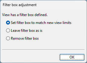
If the drawing view has a filter box defined in the Filter settings, the Filter box adjustment dialog opens.
Select the appropriate option and click OK.
-
Set filter box to match new view limits – Select this option to resize the filter box so that it matches the new view limits. Objects within the view area and the filter box are visible unless they are hidden by a Content Rule.
-
Leave filter box as is – Select this option to keep the filter box unchanged. Objects within the view area but outside the filter box are not visible in the view.
-
Remove filter box – Select this option to remove the filter box. Objects within the view area are visible unless they are hidden by a Content Rule.
-
-
The drawing view is regenerated. Click Remove Hidden Lines to remove hidden lines from the view.
Add objects, extending view box
You can add objects to a drawing view. If the current view limits do not cover the new objects, the view area is expanded to include them. If the view has a filter box, it is expanded as needed to include the new objects.
Prerequisites
-
An open work view.
Do the following:
-
In the Drawing Views dialog, select the drawing view to modify.
-
Select Modify > Add objects, extending view box.
-
If the drawing view includes a filter box, you are prompted that it will be adjusted to fit the selected objects. Click OK.
-
In the active work view, select the model objects to add to the drawing view, and press Enter.
Note: Selecting an object hidden by a Content Rule does not make it visible, but the view limits and the filter box may still be adjusted to include it.
-
The drawing view is regenerated. Click Remove Hidden Lines to remove hidden lines from the view.
Advanced view properties
You can modify the properties of a drawing view.
Do the following:
-
In the Drawing Views dialog, select the drawing view whose properties you want to modify.
-
Select Modify > Advanced view properties. The Set Properties of View dialog opens.
-
Modify the properties as required, and click OK.
-
If the drawing view was regenerated, click Remove Hidden Lines to remove hidden lines from the view.
Settings
In the Drawing views dialog, the Settings button opens a menu with the following tools.
Rename | Add view name annotation | Select line attribute style | Change line attributes | Set color style | Set Z reference plane | Set centerline NS limit | Set scale | Set reference point
Rename
You can rename closed drawing views.
Do the following:
-
In the Drawing Views dialog, select the drawing views to rename. If the selection includes open drawing views, they will not be renamed.
-
Select Settings > Rename.
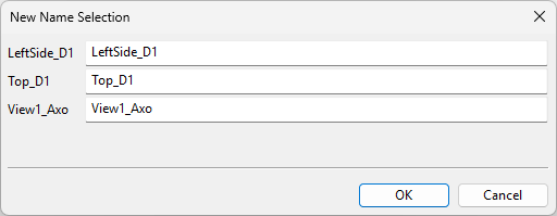
-
In the New Name Selection dialog, enter the new names, and click OK.
Add view name annotation
You can add an annotation that displays the current name and scale of a drawing view. The annotation is automatically placed below the associated drawing view and formatted using the Annotation Property Defaults of the active page.
Do the following:
-
In the Drawing Views dialog, select the drawing views to which to add the annotation.
-
Select Settings > Add view name annotation. The annotation is added to the specified views, below the bounding box of the displayed objects.
-
You can use the tools on the Drafting tab to modify, format, and move the annotation text.
Note: If you rename or rescale a drawing view, the annotation text is regenerated and any manual text edits are lost, but the formatting and location are retained.
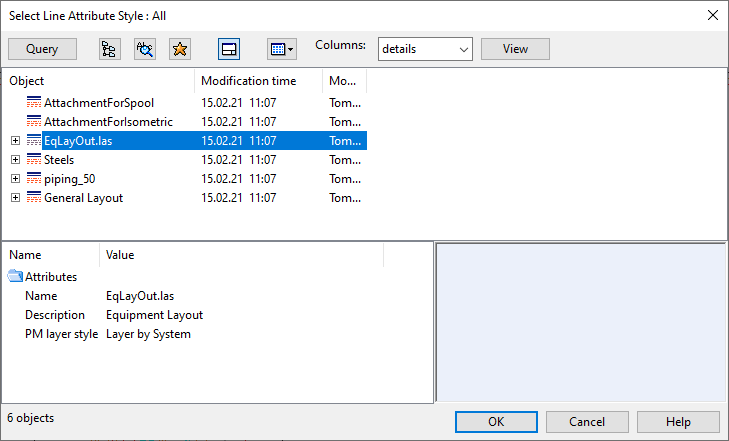
Select line attribute style
The line attribute style defines how a drawing view visualizes the edges, the hidden lines, and the centerlines of 3D objects. The line attribute style is linked to a layer style that determines to which layers the 3D objects will be assigned when the drawing is exported.
Note that the line attribute style is not applied to 2D drafting objects or annotations—their visualization is defined in tool-specific lineweight settings, as described in Annotation Properties.
Prerequisites
-
The project administrator has created the required line attribute style, as described in Line Attribute Styles.
Do the following:
-
In the Drawing Views dialog, select the drawing views to modify.
-
Select Settings > Select line attribute style. The Select Line Attribute Style dialog opens.
-
Select the style from the list and click OK.
-
If you have manually set line attributes, you are prompted whether to set them to the default style.
Change line attributes
You can change the line attributes of a set of objects in a drawing view.
Prerequisites
-
An open work view.
Do the following:
-
In the Drawing Views dialog, select the drawing views to modify.
-
Select Settings > Change line attributes. The active work view is displayed.
-
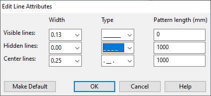
Select the required objects and press Enter. The Edit Line Attributes dialog opens.
-
Edit the line attribute values as required and click OK.
-
Regenerate the views.
Set color style
You can set model objects in drawing views to be colored based on their system, their current owner, or surface shading rules.
Do the following:
- In the Drawing Views dialog, select the drawing views to modify.
-
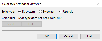
Select Settings > Set color style. The Color style setting for view… dialog opens.
-
Select what defines the color of the model objects:
-
By system – Select this to color the objects based on the System they use. For information on defining system colors, see Creating systems.
-
By owner – Select this to color the objects based on who owns them. For more information, see Color objects by ownership.
-
Use rule – Select this to color the objects based on a Surface shading style.
-
Select – Opens a list of available surface shading styles for selecting which style to use.
-
Edit – Opens the current style for editing.
-
-
-
Click OK.
Set Z reference plane
CADMATIC allows coordinates to be defined and displayed as relative to a reference plane. In drawing views, coordinate labels that show Z coordinates are normally referring to the nearest reference plane in Z direction, so the nearest plane can be, for example, either the floor or the ceiling. Set Z reference plane allows you to define the specific Z reference plane that each drawing view should use.
In the Drawing Views dialog, select one or more drawing views (hold down Ctrl or Shift to multi-select views), and then select Settings > Set Z reference plane. The Reference Z Plane dialog opens for selecting the plane to use.

After selecting the reference plane, you can open the drawing's annotation view and add coordinate labels whose coordinates are relative to a Z reference plane. Coordinates are relative to a Z reference plane when the label definition uses specific tags for data requests. Those tags are described in Attributes for label definitions using Z reference plane.
In the following example a label definition has been configured to use the data requests .Dx;-1;;.Dw;-1;;.Dv;-1;; to show distance, direction, and plane name in the third row of the coordinate label, and a label of this type has been added to the connection point of a valve. The sample image on the left shows what the label displays when the reference plane is set to "BASE" (located at 0.0 mm), while in the image on the right the reference plane is "TT" (located 1010.0 mm above "BASE").

|

|
For information on creating and editing label definitions, see Label Definitions.
For information on creating and editing Z reference planes, see Coordinate references.
Set centerline NS limit
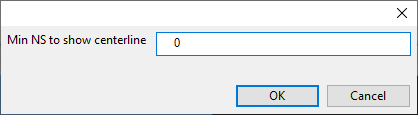
You can specify a minimum Nominal Size value for visualizing the pipe centerlines. If a pipe is smaller than this value specifies, then the centerline is not visualized.
Do the following:
-
In the Drawing Views dialog, select the drawing views to modify.
-
Select Settings > Set centerline NS limit. A dialog opens for defining the limit.
-
Enter the required value and click OK.
-
Regenerate the views.
Set scale
You can change the scale of a drawing view. If you do this before adding any views to the page, the scale of the first view you add to the page stores the scale in the document header, in the attribute "Drawing Main Scale" (.IR) or "Drawing Detail Scale" (.IS).
Do the following:
-
In the Drawing Views dialog, select the view whose scale to change.
-
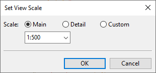
Select Settings > Set scale. The Set View Scale dialog opens.
-
Select the scale:
-
Main / Detail – Select a scale that the administrator has defined in the General Drawing settings.
-
Custom – Specify the scaling value. (This is the only possible option if main view/detail view scales are not applicable to the document type.)
-
-
Click OK.
Set reference point
You can change the reference point of a drawing view. The reference point is displayed as a cross-hair when you insert or move the drawing view on the page, and its default location is the center of the view.
Do the following:
-
In the Drawing Views dialog, select the drawing view to modify.
-
Select Settings > Set reference point.
-
Pick a new reference point from the 3D model.
Add to Current Page
You can select a view from the drawing view list and insert it to a suitable location on the active page. By default, the reference point is at the center of the view. You can change the reference point of a given view as described in Set reference point.
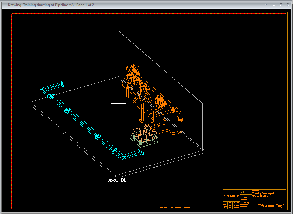
As you are placing the view on the page and moving it to the intended position, the preview image can show:
-
The bounding box around the view. You can enable or disable the displaying of the bounding box from the document settings, as described in Settings.
-
The 3D objects in the view. You can enable or disable this from the context menu of the tool, as described below.
If the first view that you add to the document has a main scale or detail scale, the scale value is stored in the attribute "Drawing Main Scale" (.IR) or "Drawing Detail Scale" (.IS), respectively. Any other view that you add later does not change the value of that attribute. Removing all views clears the attribute.
Do the following:
-
In the Drawing Views dialog, select the required view from the list and then click Add to Current Page. The drawing view is displayed on the page; the cross-hair indicates where the reference point is.
-
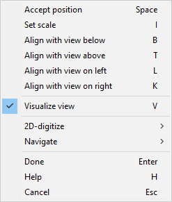
Start moving the drawing view to its intended location. If the view is large and complicated and does not move smoothly, disable the Visualize view (V) option from the context menu and see if that helps.
-
Press I or select Set scale from the context menu and use the Set View Scale dialog to specify the scale of the drawing view on the page.
-
If the page already contains another drawing view that uses the same projection and same global coordinates as the view you are adding, you can use the Align with… context-menu commands to align the views. The views are aligned based on the global axis that is parallel to the U or V axis.
-
When the view is in the intended location, press Enter or Space to accept the location and return to the Drawing Views dialog.
Remove from Page
You can remove a drawing view from the page it is assigned to. Removing all views from a page clears the scale value that has been stored in the document header, in the attribute 'Drawing Main Scale' (.IR) or 'Drawing Detail Scale' (.IS).
Do the following:
-
In the Drawing Views dialog, select the view to remove from its page.
-
Click Remove from Page. You are prompted to confirm the action.
Tip: You can also remove drawing views with the Home tab command Remove from page.
Open
You can open drawing views to display each view in full size in a separate window.
Do the following:
-
In the Drawing Views dialog, select the views to open.
-
Click Open. The views are opened and their state becomes 'Open'.
Close
You can close drawing view windows that are currently open.
Do the following:
-
In the Drawing Views dialog, select the views to close.
-
Click Close. The views are closed and their state becomes 'Closed'.
Regenerate
You can apply the latest changes in the 3D model to drawing views by regenerating them. You should regenerate drawing views when their status is 'Outdated'.
Do the following:
-
In the Drawing Views dialog, select the views to regenerate.
-
Click Regenerate. The view status becomes 'Ok, has hidden lines'.
-
Use Remove Hidden Lines on the views if needed.
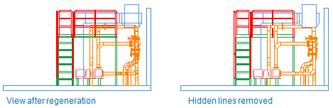
Remove Hidden Lines
A hidden line is an edge or boundary of a 3D object that lies behind a visible surface and is normally not visible to the eye. Hidden line removal removes these lines, which usually provides a more realistic representation of the spatial relations of the objects in the view. The lines are restored if you regenerate the view.
Do the following:
-
In the Drawing Views dialog, select the views to include in hidden line removal.
-
Click Remove Hidden Lines. The view status becomes 'Ok'.
Delete
You can delete drawing views that are no longer needed.
Do the following:
-
In the Drawing Views dialog, select the views to delete.
-
Click Delete. You are prompted to confirm the action.
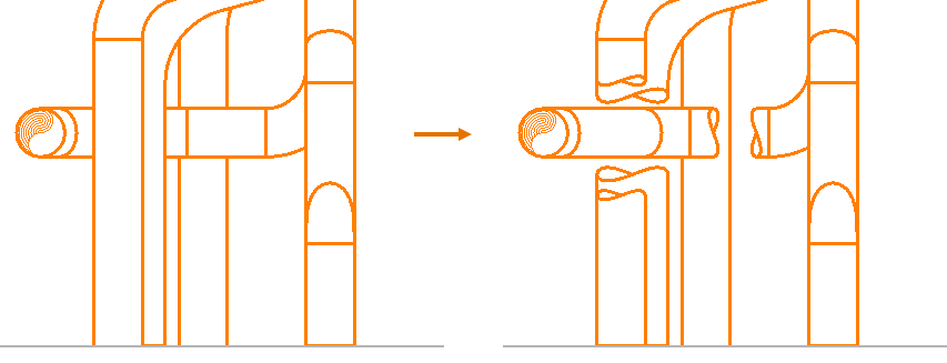
Hiding Boxes
You can use hiding boxes to visually cut parts of straight pipes. This is useful when the frontmost pipes are blocking the view of objects that you want to be visible in the drawing.
Create
You can add hiding boxes to straight pipes in a drawing view to reveal objects behind them. You can use a single hiding box for multiple parallel pipes, or you can use a separate hiding box for each pipe.
In this example, three hiding boxes are used: two for vertical pipes and one for the horizontal pipe. A longer cut on the frontmost vertical pipe and a shorter cut on the vertical pipe behind it create a depth effect through the cuts.
Do the following:
-
In the Drawing Views dialog, select the drawing view to modify.
-
Select Hiding Boxes > Create.
-
In the drawing view, click each pipe to hide with the same hiding box, and press Enter. The hiding box and its grip points are displayed in the view.
-
To resize the hiding box, click a grip point and then click the intended new location.
-
When the hiding box is ready, press Enter.
-
Add another hiding box in the same way, or press Esc to exit the tool.
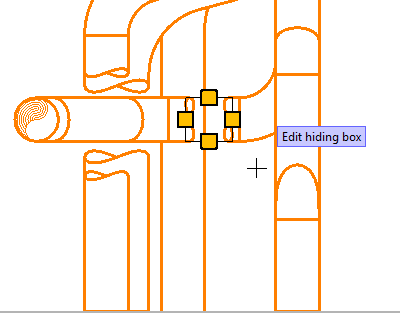
Edit
You can move and resize hiding boxes by adjusting their grip points.
Do the following:
-
In the Drawing Views dialog, select the drawing view to modify.
-
Select Hiding Boxes > Edit. The drawing view displays the hiding boxes as rectangles.
-
Click the hiding box to modify. Its grip points are displayed in the view.
-
Click a grip point and then click the intended new location to modify the hiding box as needed.
-
When the hiding box is ready, press Enter.
-
Select another hiding box to modify, or press Esc to exit the tool.
Delete
You can delete hiding boxes that are no longer needed.
Do the following:
-
In the Drawing Views dialog, select the drawing view to modify.
-
Select Hiding Boxes > Delete. The drawing view displays the hiding boxes as rectangles.
-
Click each hiding box to delete, and press Enter to confirm the deletion.
Content Rule
A content rule is a query-based filter that defines which objects are shown in a given view. The query can specify, for example, that only piping objects and equipment are shown in the view. Content rules can be created for work views and drawing views.
You can create a content rule for selected drawing views; the rule is saved in the properties of each view. To enable reuse, you can store the rule in COS or in a private file.
If you clear the view setting Filter > Show objects matching content rule, the content rule is removed from the view.
Tip: You can also manage content rules on the Drafting tab, as described in Visualization and changes.
Create | Edit | Copy from another view | Copy from view in another drawing | Import from COS/file | Delete
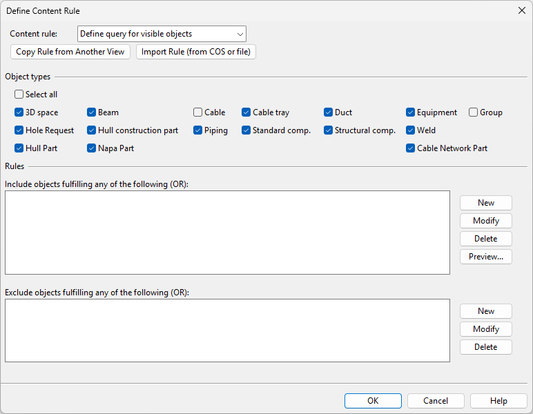
Create
You can create a content rule for one or more drawing views. If a drawing view already has a content rule, the new rule replaces the existing rule.
Do the following:
-
In the Drawing Views dialog, select the drawing views to which to apply the content rule.
-
Select Content Rule > Create. The Define Content Rule dialog opens.
-
Use the query editor to define a query that selects the objects that you want to see in the views, as described in Define Content or Transparency Rule, or use the Copy Rule from Another View or Import Rule (from COS or file) functions to apply an existing query.
-
Click Save As and select where to save the query:
-
Click COS to save it as a project query that also other designers can import to any document in the same project.
-
Click File to save it as a private query that is only available to you.
-
-
Click OK to close the query editor.
Edit
You can edit the content rule of a drawing view.
Do the following:
-
In the Drawing Views dialog, select the drawing view whose content rule to edit.
-
Select Content Rule > Edit. The query editor opens.
-
Edit the rule as required, and click OK.
Copy from another view
You can copy an existing content rule from another drawing view in the same document.
Do the following:
-
In the Drawing Views dialog, select the drawing views to which to apply the content rule.
-
Select Content Rule > Copy from another view. The Select view with content rule dialog opens.
-
Click the name of the view from which to copy the content rule. The query editor opens, displaying the copied query.
-
Edit the query if needed, and then click OK.

Copy from view in another drawing
You can copy an existing content rule from a drawing view in another document.
Do the following:
-
In the Drawing Views dialog, select the drawing views to which to apply the content rule.
-
Select Content Rule > Copy from view in another drawing. An object browser dialog opens, listing all available documents.
-
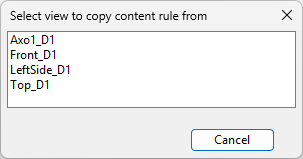
Select the document from which to copy the content rule, and click OK. The Select view to copy content rule from dialog opens.
-
Click the name of the view from which to copy the content rule. The query editor opens, displaying the copied query.
-
Edit the query if needed, and then click OK.
Import from COS/file
You can import an existing content rule from COS or a query file.
Do the following:
- In the Drawing Views dialog, select the drawing views to which to apply the content rule.
-
Select Content Rule > Import from COS/file. The Import Query dialog opens.
-
Select the query to be imported:
-
To import the content rule from a project query stored in COS, click COS, select the query from the object browser, and click OK.
(If there is no suitable query in COS, select Query > Advanced to create one.)
-
To import the content rule from a private query stored in a .qsr file, click File, select the file from the list, and click OK.
(If there is no suitable query file, click New to create one.)
The query editor opens, displaying the imported query.
-
- Edit the query if needed, and then click OK.

Delete
You can delete content rules from drawing views.
Do the following:
-
In the Drawing Views dialog, select one or more drawing views that have a content rule.
-
Select Content Rule > Delete.
Transparency Rule
A transparency rule is a query-based filter that defines which objects are shown as transparent in a given drawing view. The query can specify, for example, that Hull objects are shown as transparent.
You can create a transparency rule for selected drawing views; the rule is saved in the properties of each view. To enable reuse, you can store the rule in COS or in a private file.
Tip: You can also manage transparency rules on the Drafting tab, as described in Visualization and changes.
Create | Edit | Copy from another view | Copy from view in another drawing | Import from COS/file | Delete
Create
You can create a transparency rule for one or more drawing views. If a drawing view already has a transparency rule, the new rule replaces the existing rule.
Do the following:
-
In the Drawing Views dialog, select the drawing views to which to apply the transparency rule.
-
Select Transparency Rule > Create. The Define Transparency Rule dialog opens.
-
Use the query editor to define a query that selects the objects that you want to see as transparent in the views, as described in Define Content or Transparency Rule, or use the Copy Rule from Another View or Import Rule (from COS or file) functions to apply an existing query.
-
Click Save As and select where to save the query:
-
Click COS to save it as a project query that also other designers can import to any document in the same project.
-
Click File to save it as a private query that is only available to you.
-
-
Click OK to close the query editor.
Edit
You can edit the transparency rule of a drawing view.
Do the following:
-
In the Drawing Views dialog, select the drawing view whose transparency rule to edit.
-
Select Transparency Rule > Edit. The query editor opens.
-
Edit the rule as required, and click OK.
Copy from another view
You can copy an existing transparency rule from another drawing view in the same document.
Do the following:
-
In the Drawing Views dialog, select the drawing views to which to apply the transparency rule.
-
Select Transparency Rule > Copy from another view. The Select view with transparency rule dialog opens.
-
Click the name of the view from which to copy the transparency rule. The query editor opens, displaying the copied query.
-
Edit the query if needed, and then click OK.
Copy from view in another drawing
You can copy an existing transparency rule from a drawing view in another document.
Do the following:
-
In the Drawing Views dialog, select the drawing views to which to apply the transparency rule.
-
Select Transparency Rule > Copy from view in another drawing. An object browser dialog opens, listing all available documents.
-
Select the document from which to copy the transparency rule, and click OK. The Select view to copy transparency rule from dialog opens.
-
Click the name of the view from which to copy the transparency rule. The query editor opens, displaying the copied query.
-
Edit the query if needed, and then click OK.
Import from COS/file
You can import an existing transparency rule from COS or a query file.
Do the following:
- In the Drawing Views dialog, select the drawing views to which to apply the transparency rule.
-
Select Transparency Rule > Import from COS/file. The Import Query dialog opens.
-
Select the query to be imported:
-
To import the transparency rule from a project query stored in COS, click COS, select the query from the object browser, and click OK.
(If there is no suitable query in COS, select Query > Advanced to create one.)
-
To import the transparency rule from a private query stored in a .qsr file, click File, select the file from the list, and click OK.
(If there is no suitable query file, click New to create one.)
The query editor opens, displaying the imported query.
-
- Edit the query if needed, and then click OK.
Delete
You can delete transparency rules from drawing views.
Do the following:
-
In the Drawing Views dialog, select one or more drawing views that have a transparency rule.
-
Select Transparency Rule > Delete.